To open a new drawing window (shown in Figure 4), click the New Control Display
button in the Vdraw Toolbox or select New on the File menu in the menu bar. You will start drawing objects and creating control tools in this drawing window.
Figure4 - New drawing window
Placing a Grid in the Drawing Window
A grid in the drawing window helps you align the objects you create. To add a grid to the drawing window select on the toolbar
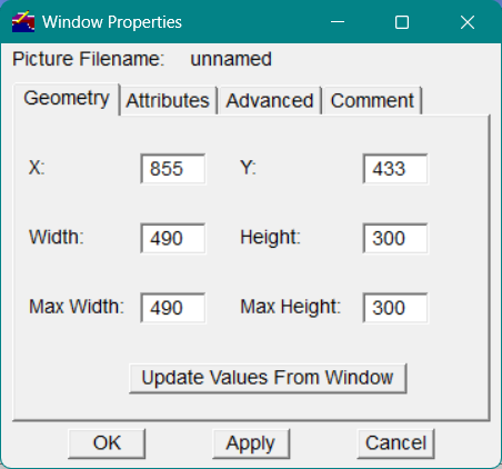
The grid size can be changed in the Window Properties dialog. Select the Window menu and then select Properties...
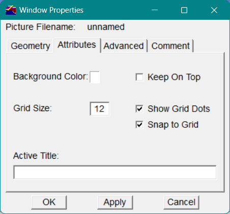
Figure5 - Window Properties
The Window Properties dialog appears as shown in Figure 5
Figure6 - Windows Properties Attributes
In the Window Properties dialog, select the Attributes tab. In the Grid Size field, enter a value, in pixels, to specify the density of the grid. Here, enter 12.
1. To display a grid in the drawing window, check the Show Grid Dots checkbox .
2. To activate the grid so that objects snap to the grid points as you create them, check the Snap to Grid checkbox.
3. If you want the control display window to have a specific title when the window is activated, enter the title in the Active Title field. Here, enter Furnace Control Display.
4. Click OK to execute the options you selected. The grid should now appear in the drawing window.
Creating the Furnace Object
To begin drawing in the Furnace Control Display window, click the Rectangle drawing tool button in the Vdraw Toolbox.
To create the furnace object
Position the mouse pointer in the drawing window where you want to begin drawing the furnace object.
1. Press and drag the mouse pointer diagonally to create a rectangle.
2. When the furnace object is the size you want, release the mouse button.
Figure7 - Example of a furnace object and grid
Furnace Object
Grid
To edit an object, in the Vdraw Toolbox, click the Pointer tool.
Using the Pointer tool, click in the object you want to edit to select it.
Place the Pointer tool within the object and click the right mouse button to display the pop-up editing menu for that object.
On the editing menu, select an option and edit the selected object.
Labeling the Furnace Object
To label the furnace object, click the Text drawing tool button in the Vdraw Toolbox.
Place the mouse pointer where you want the text to begin (here, place the mouse pointer within the furnace object) and click the mouse button to display the text entry box.
Figure8 - Text entry box
Begin typing to enter text. Here, enter Furnace to create the label "Furnace" within the furnace object. If you do not like the starting location for the text, select Cancel and try again.
To correct a typing error, press the BACK SPACE or DELETE key and retype the text.
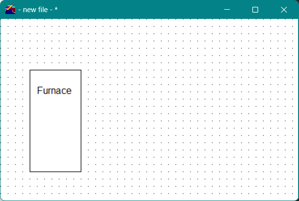
Click OK . The drawing window should appear as shown in Figure 9.
Figure9 - Furnace object with label
To change the appearance of text
In the Vdraw Toolbox, click the Pointer tool.
1. Using the Pointer tool, select the text you want to modify. The selection rectangle surrounds the text.
2. Then click the Properties button in the Vdraw Toolbox or on the Object menu in the menu bar, select Properties.
Figure10 - Text properties
The Graphic Properties dialog appears (showing the Text tab), as shown in Figure 10. In the Graphic Properties dialog, you can modify such attributes of the text as font, color, and size.
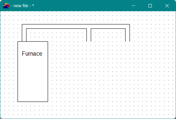
Creating the Ducts
To create the ducts connecting the furnace to the two rooms, as shown in Figure 11, click the Constrained Line drawing tool button in the Vdraw Toolbox. With this drawing tool, you can draw three styles of straight lines: slanted, vertical, and horizontal.
To create the furnace ducts
Position the mouse pointer where you want the line to begin.
1. Drag the mouse pointer until the line is the appropriate length.
If you move the mouse in a circular motion while continuing to press the mouse button, the line rotates at 45-degree angles relative to its starting position.
1. When the line is the desired length and angle, release the mouse button.
2. Continue using the Constrained Line drawing tool to draw the rest of the duct lines. The furnace control display window should appear as shown in Figure 11.
Note To delete a line, select the line (using the Pointer tool) and press either the DELETE key or the BACK SPACE key, depending on the configuration of your keyboard.
Figure11 - Furnace ducts
Saving the Drawing Window
Vdraw provides a way to periodically save a drawing window while you are creating it.
To save a drawing window
In the Vdraw Toolbox, click the Save button.
-or-
On the File menu in the menu bar, select Save .
1. In the File name field of the Save As window, enter the filename furnace_tutor, then select the directory in which you want to save the control display file.
2. Click Save to save the file.
From now on, each time you save this file, the filename automatically displays in the File name field. We encourage you to save your files frequently.
Note It is not necessary to specify a file extension; Vdraw gives the file the appropriate file extension, .vcd, for Vsystem control display.
 on the toolbar
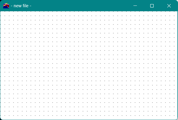
 tool button in the Vdraw Toolbox.
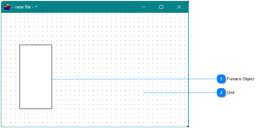
 in the Vdraw Toolbox.
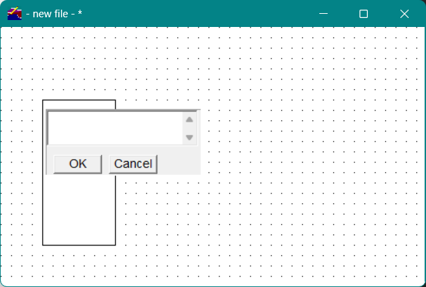
 in the Vdraw Toolbox or on the Object menu in the menu bar, select Properties.
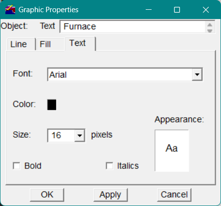
 drawing tool button in the Vdraw Toolbox. With this drawing tool, you can draw three styles of straight lines: slanted, vertical, and horizontal.