Adding Control Tools to the Application
You use the control tool buttons in the Vdraw Toolbox to create control tools. Control tools dynamically connect to the Vsystem database and enable you to monitor and control equipment from any workstation on the network.
For this tutorial, the first control tool you will place in the drawing window is a button that turns the furnace on and off. Buttons are binary control devices, so they are appropriate for situations in which an object needs to toggle between "on" and "off."
Creating Button Control Tools
To create a button control tool, select the Button control tool  .
.
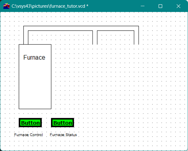
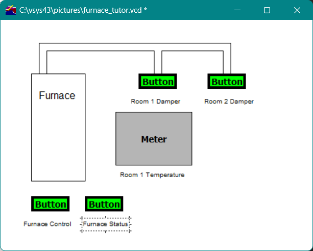
In the drawing window below the furnace object, hold the mouse button and drag the mouse pointer to draw a box the size you want the activated Button control tool to be, as shown below
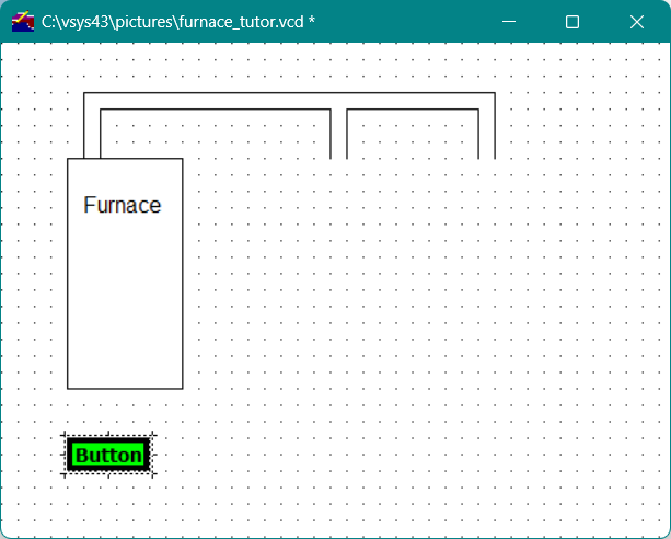
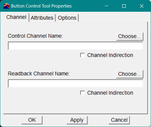
When you release the mouse button, the Button Control Tool Properties dialog appears. A control tool dialog provides a form for specifying all of the information necessary to configure the control tool.
Once you have created a Button control tool in the drawing window, you can use the editing tools to create additional buttons.
For this tutorial, specify the following options in the Button Control Tool Properties dialog:
Control Channel Name
Control channels are output channels that attach to and control the hardware. On the Channel tab, in the Control Channel Name field, enter the name of the control channel to which you want to connect the Button control tool, in this case, tutor::furnace_control.
Note You must specify the database name (tutor) , followed by double colons (::), before the name of a channel (furnace_control) in a specified database.
|
You can also use the Choose button to specify the control channel. Click the Choose button above the Control Channel Name field. In the Database field of the Channel Selector window, enter the name of the database you created for the furnace application, tutor , and press ENTER on the keyboard. The tutor database name displays in the list box, along with all of the channels you defined in the tutor database, as shown in Figure 12
Figure12 - Channel Selector window, showing database channels
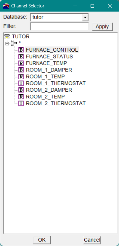
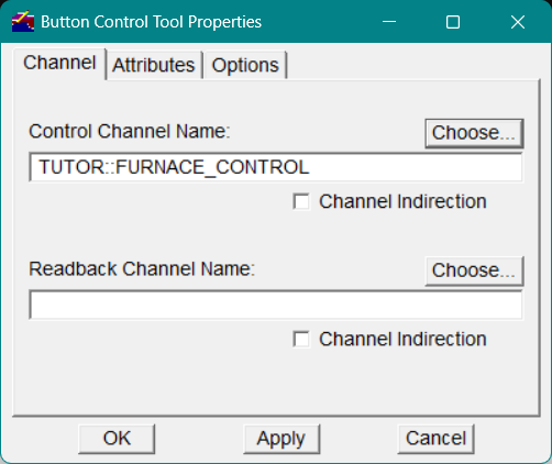
Select the furnace_control channel; the channel name becomes highlighted. Then click OK to apply your selection to the Button Control Tool Properties dialog. The selected tutor::furnace_control channel name now displays in the Control Channel Name field, as shown in Figure 13
Figure13 - Channel name displayed in Button Control Tool Properties dialog
Button Type
A toggle button switches a channel between its two binary states, while a push button places the channel into a true (B1) state as long as the mouse button is depressed. When you release the mouse button, the channel is set to a false (B0) state.
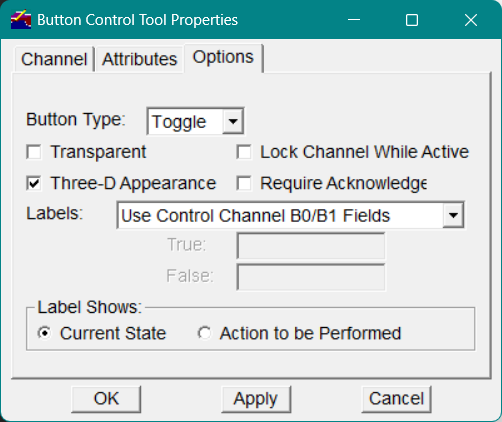
Select the Options tab in the Button Control Tool Properties dialog as shown in Figure 14 and specify the button type for your Button control tool by selecting Toggle from the Button Type drop-down list.
To create a three-dimensional button that more clearly shows its pushed (on) and nonpushed (off) state, click the Three-D Appearance checkbox.
Figure14 - Button Control Tool Properties Options tab
Click OK to apply your selection to the new Button control tool. The box you drew in the drawing window is now labeled "Button" in the window. To modify the text of the button label, select the Attributes tab in the Button Control Tool Properties dialog.
Labeling Button Control Tools
After you have created the first Button control tool, use the Text drawing tool button in the Vdraw Toolbox to create the label "Furnace Control."
In the Vdraw Toolbox, click the Text drawing tool  .
.
1. Place the mouse pointer where you want the text to begin, below the Button control tool, and click the mouse button to display the text entry box.
2. In the text entry box, enter Furnace Control .
3. Click OK .
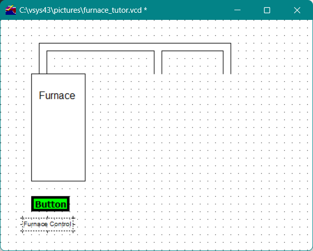
The drawing window should appear as shown in Figure 15
Figure15 - Labeled Button control tool
To modify the text in the label
Select the label with the Pointer tool.
1. In the Vdraw Toolbox, click the Properties button.
-or-
On the Object menu in the menu bar, select Properties.
-or-
On the pop-up editing menu, select Properties.
1. In the Graphic Properties dialog, make your text modifications.
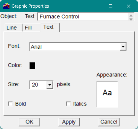
Note Once you have created a control tool, you can use the editing options to resize or reposition it, as described in the next section.
|
Creating Additional Button Control Tools Using the Editing Options
You can use the Button control tool you just created to create additional Button control tools. By using one button to create another, you save time and maintain size consistency.
To copy the Furnace Control Button control tool
Using the Pointer tool, select the Button control tool you just created.
-
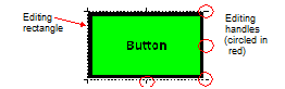
The editing rectangle frames the object, as shown in Figure 16
-
Click the right mouse button to display the pop-up editing menu.
-
On the menu, select Copy. The copy of the control tool will not activate (appear) until you either move it or paste it, as described in step 4.
-
To reposition the new Button control tool, do one of the following:
-
With the mouse pointer on the middle right handle of the editing rectangle surrounding the Button control tool, press and drag the mouse pointer to the desired location for the control tool, then release the mouse button. (See Figure 14 for an illustration of the editing handles on the editing rectangle.)
-or-
-
Deselect the control tool by placing the mouse pointer outside of the editing rectangle and clicking the mouse button; then select Paste from the pop-up editing menu.
Figure16 - Editing rectangle and handles
A new Button control tool appears at the selected location. Figure 17 shows the drawing window with the original Button control tool duplicated.
Now you will assign a different channel to the newly created Button control tool. The editing rectangle should still be framing the new Button control tool; if it is not, click the Pointer tool in the Vdraw Toolbox and then select the Button control tool in the drawing window to produce the editing rectangle.
Figure17 - Button control tool duplicated

To assign a channel to the new Button control tool
-
In the Vdraw Toolbox, click the Properties button.-or-On the Object menu in the menu bar, select Properties.
-
In the Control Channel Name field of the Button Control Tool Properties dialog, change the channel name to tutor::furnace_status . You can also use Choose to select this channel from the channel list in the specified database.
-
Click OK to complete the modification.
-
The drawing window should now contain two Button control tools below the furnace object.
Next, you will add the label "Furnace Status" to the second Button control tool.
To label the second Button control tool
-
Following the instructions above for copying the Button control tool, copy the label of the first Button control tool to a position beneath the second Button control tool.
-
With the duplicated label still selected, in the Vdraw Toolbox, click the Properties button or on the Object menu in the menu bar, select Properties .
-
In the Graphic Properties dialog that appears, in the Text field, change the text of the label to Furnace Status, then select OK.
Figure18 - Drawing window with two Button control tools
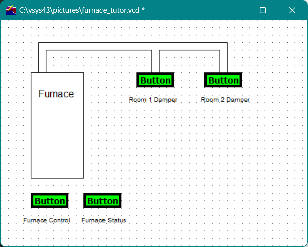
The control tools that control the dampers for Room 1 and Room 2 are also buttons. These two Button control tools are located to the right of the furnace object. The Button control tool closest to the furnace controls Room 1.
To create the two Button control tools that control the dampers
-
Use the editing options to copy an existing Button control tool and move it to the base of the left duct.
-
With the new Button control tool still selected, click the Properties button in the Vdraw Toolbox.-or-On the Object menu in the menu bar, select Properties.
-
In the Control Channel Name field of the Button Control Tool Properties dialog, change the control channel to tutor::room_1_damper; or, use Choose to select this channel from the channel list.
-
Add the label Room 1 Damper to the Button control tool by copying and changing the label of the Furnace Control button.
-
Copy the Room 1 Damper Button control tool and move it to the base of the right duct.
-
Repeat step 2 above.
-
In the Control Channel Name field, change the control channel to tutor::room_2_damper; or, use Choose to select this channel from the channel list.
-
Add the label Room 2 Damper to the Button control tool by copying and changing the label of the Room 1 Damper button.The furnace drawing window now displays all of the Button control tools defined, as shown below.
Figure19 - Completed Button control tools
To save the drawing window
-
In the Vdraw Toolbox, click the Save button.
-or-
-
On the File menu in the menu bar, select Save.
Adding Meter Control Tools to the Application
Meters and dials are control and monitoring devices for double-precision floating-point, integer, and real channel types.
To create a Meter control tool
-
Click the Meter control tool button
 in the Vdraw Toolbox and move the mouse pointer to the drawing window.
 -
Drag a box the size you want the meter to be, as shown.
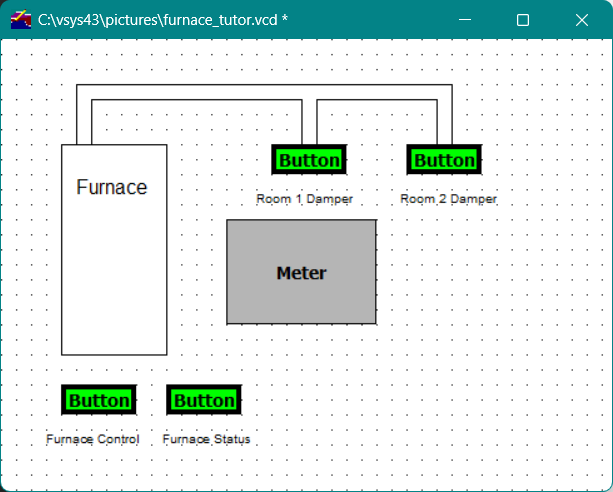 Note The size of the meter box determines the appearance of the activated meter; the software tries to make a best-fit based on the parameters of the meter. For example, if you create a box that is too large, the meter will appear off-center within the box when activated. If you are not happy with the appearance of the activated meter, resize the meter box until it has the look you desire.
When you release the mouse button, the Meter Control Tool Properties dialog appears, as shown below.
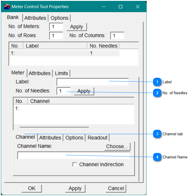
As you can see in the dialog, there are numerous options from which to choose when you define a Meter control tool; however, for this tutorial, you will create a simple style of meter. The first meter you will create serves as a temperature gauge for Room 1.
For this tutorial, specify the following options in the Meter Control Tool Properties dialog:
Changing the Needle Color and Style
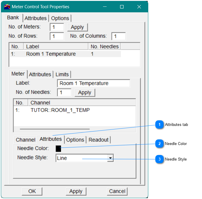
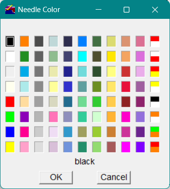
Needle ColorTo change the color of a needle, click the color box next to Needle Color to display the Needle Color window. In the Needle Color window, Figure 22, click on a color and then click OK .
|
Figure22 - Needle Color window
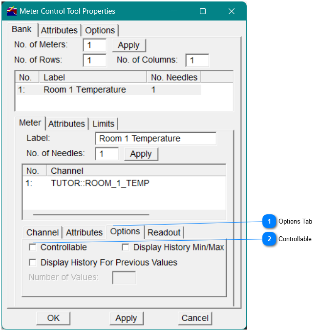
Controllable
Set the meter to controllable. When the needle of a meter is controllable, you can change the value of the Meter control tool by moving the needle on an active control display window with the mouse pointer.
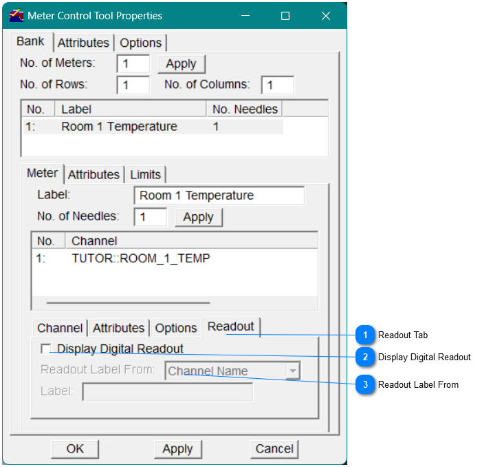
Display Digital Readout
Enable the Digital Readout
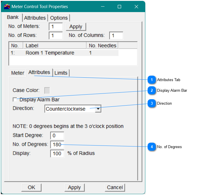
Direction
Limits
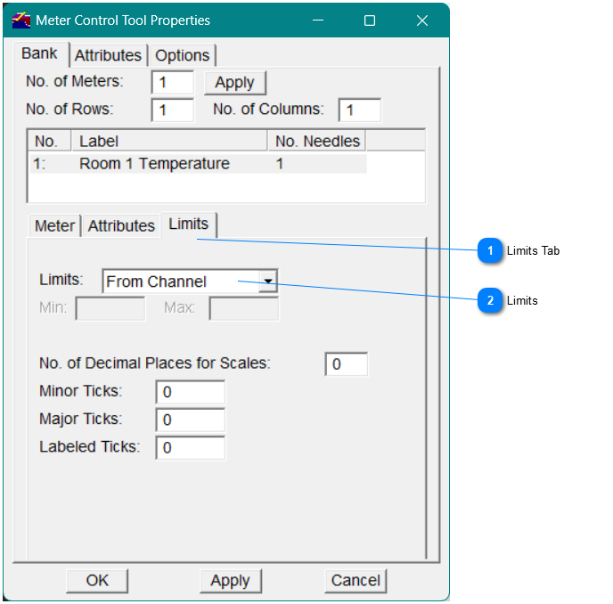
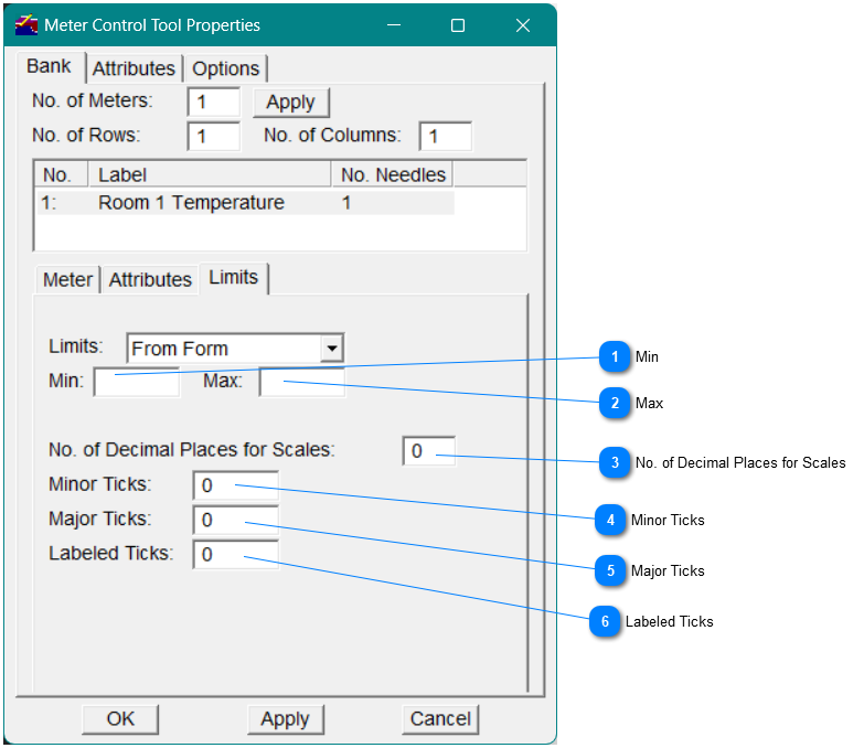
Note The value for the limit that you enter in the Min field overrides the lower display limit value (if one is defined in the Vsystem database) for the channel to which you connect the Meter control tool. The value for the limit that you enter in the Max field overrides the upper display limit value (if one is defined in the Vsystem database) for the channel to which you connect the Meter control tool.
|
|
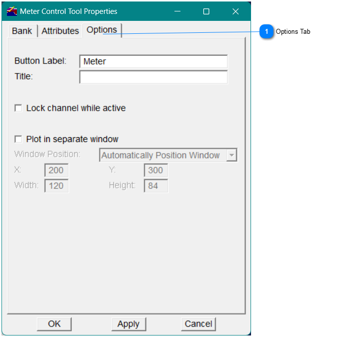
Button Label
Steps to take after creating a Meter control tool
After you have created the Meter control tool,
-
click the Text drawing tool in the Vdraw Toolbox to create the label "Room 1 Temperature".
-
Place the mouse pointer below the Meter control tool where you want the text to begin, and type Room 1 Temperature . Then click OK .
-
To modify the characteristics of the label text, select the label, then in the Vdraw Toolbox, click the Properties button.-or-On the Object menu in the menu bar, select Properties.
-
Make your modifications in the pop-up Graphic Properties dialog.The following illustration shows the first Meter control tool.
Creating Additional Meter Control Tools
To create additional Meter control tools:
-
Copy the Meter control tool by selecting it and clicking the right mouse button to display the pop-up editing menu.
-
On the menu, select Copy, then move the copy to the right of the original Meter control tool. The new Meter control tool serves as the thermostat for Room 1.
-
Select the new meter, then in the Vdraw Toolbox click the Properties button.-or-On the Object menu in the menu bar, select Properties .
-
On the Bank tab in the Meter Control Tool Properties dialog, select the Meter subtab in the middle of the dialog. In the Label field, change the label to Room 1 Thermostat.
-
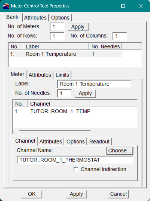
On the lower Channel subtab, in the Channel Name field, change the channel to tutor::room_1_thermostat, as shown below.
-
Click OK on the Meter Control Tool Properties dialog to apply the changes to the new Meter control tool.
-
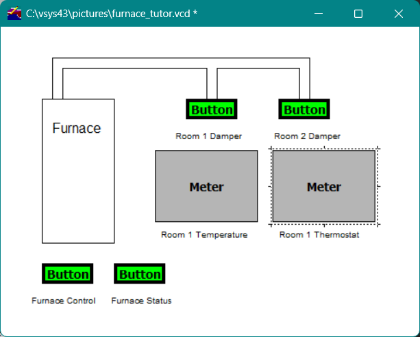
Copy the meter label Room 1 Temperature and move it below the Meter control tool for Room 1 Thermostat.
-
To change the text of the label from "Room 1 Temperature" to "Room 1 Thermostat," select the label for the second Meter control tool, then perform one of the following actions:
-
In the Vdraw Toolbox, click the Properties button.-or-
-
On the Object menu in the menu bar, select Properties .
-
In the Graphic Properties dialog that appears, in the Text field, enter the new label text.
 Note Don't forget to periodically save you file.
Adding a Bar Control Tool to the Application
Bars graphically reflect the current value of a double-precision floating-point, integer, or real channel type. Here, we will create a Bar control tool to control the temperature of Room 1.
In the Vdraw Toolbox, click the Bar control tool button.
Bar control tool
The Bar Control Tool Properties dialog appears.
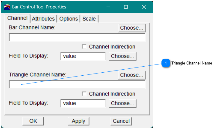
For this tutorial, you will specify the following options in the Bar Control Tool Properties dialog.
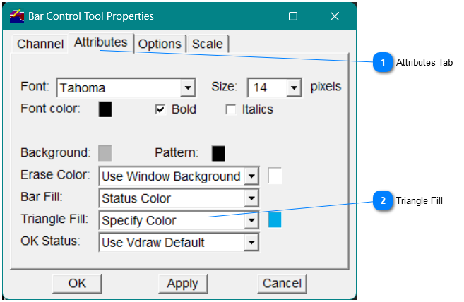
Triangle Fill
Options
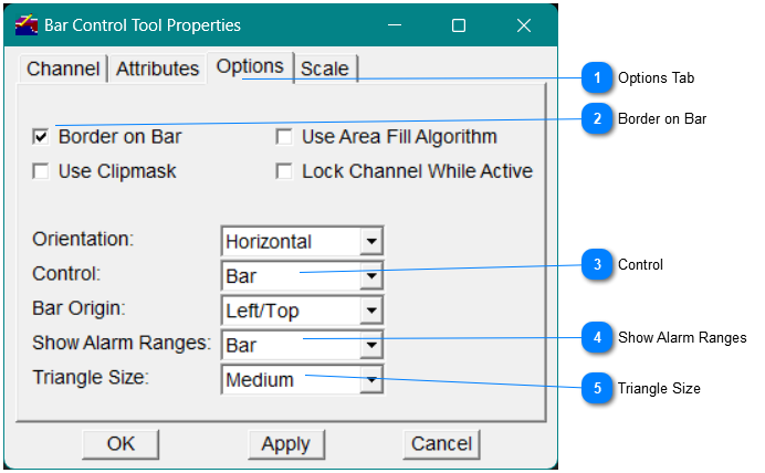
Triangle SizeFrom the Triangle Size drop-down list, select one of the options to specify the size of the triangle appearing on the Bar control tool (remember: a triangle appears only if a channel name is entered in the Triangle Channel Name field). The available triangle sizes are Small, Medium, and Large. For this tutorial, select Medium from the drop-down list.
|
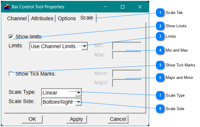
Scale Tab
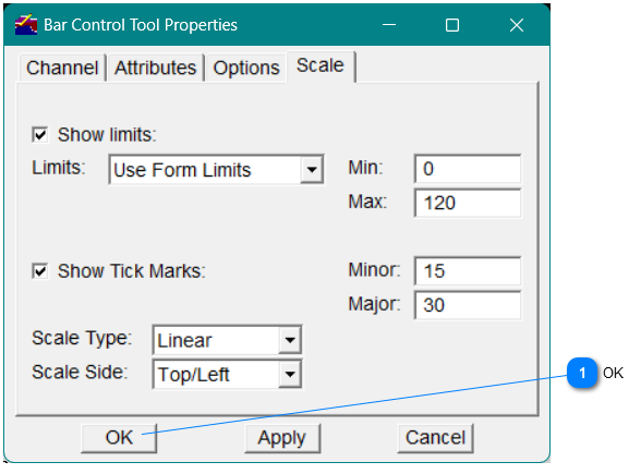
Steps to take after creating a Bar control tool
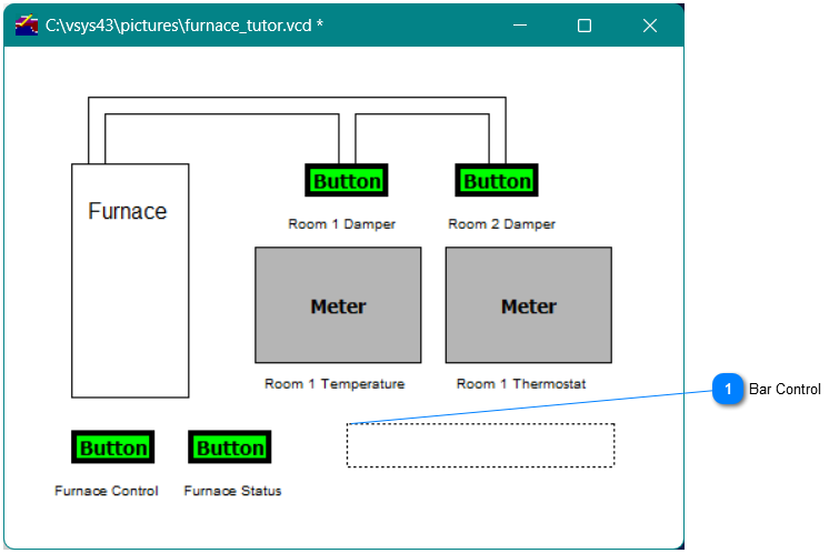
In the Vdraw Toolbox, click the Text drawing tool to label the bar Room 1 Temperature.
1. Place the label below the Bar control tool; then click OK .
2. To modify the font of the label, select the label, then in the Vdraw Toolbox, click the Properties button.
-or-
On the Object menu in the menu bar, select Properties .
Creating Additional Bar Control Tools
To Copy the Bar control tool, select it and click the right mouse button to display the pop-up editing menu.
1. Select Copy , then drag the copy below the original Bar control tool.
The new Bar control tool controls the thermostat of Room 1.
1. Select the new Bar control tool, then in the Vdraw Toolbox, click the Properties button.
-or-
On the Object menu in the menu bar, select Properties.
1. In the Triangle Channel Name field (on the Channel tab), change the channel to tutor::room_1_thermostat . Then click OK to apply the change to the new Bar control tool.
2. Copy the label Room 1 Temperature and move it below the Bar control tool for Room 1 Thermostat.
3. Change the text of the label from Room 1 Temperature to Room 1 Thermostat:
Select the label of the second Bar control tool.
1. In the Vdraw Toolbox, click the Properties button.
-or-
On the Object menu in the menu bar, select Properties.
1. In the Graphic Properties dialog that appears, in the Text field, change the text of the label to Room 1 Thermostat, then click OK .
To save the drawing window
-
In the Vdraw Toolbox, click the Save button.
-or-
-
On the File menu in the menu bar, select Save.
The drawing window now appears as shown
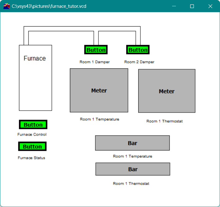
Note As you can see, the arrangement and size of some of the objects in the drawing window have changed. This was done to accommodate the information that displays on these objects when the window is activated. As you create your own objects, you will probably need to modify their size and arrangement to make the information display in a useful manner.
|